Ace Cfl Pcb Circuit Diagram

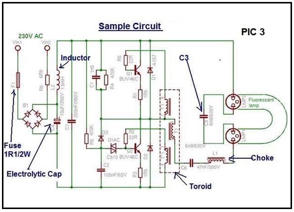
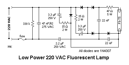
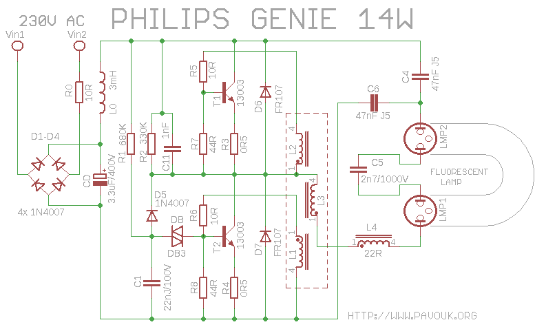
The circuit of cfl is explained in succeeding paragraphs.
Cfl pcb circuit diagram. Though being compact it efficiently performs the requirements as a choke. 2 1 block diagram the cfl circuit has been designed for a nominal mains voltage of 230 vrms 50 60 hz. The cfl pcb is quite compact and fits in the holder base.
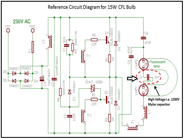
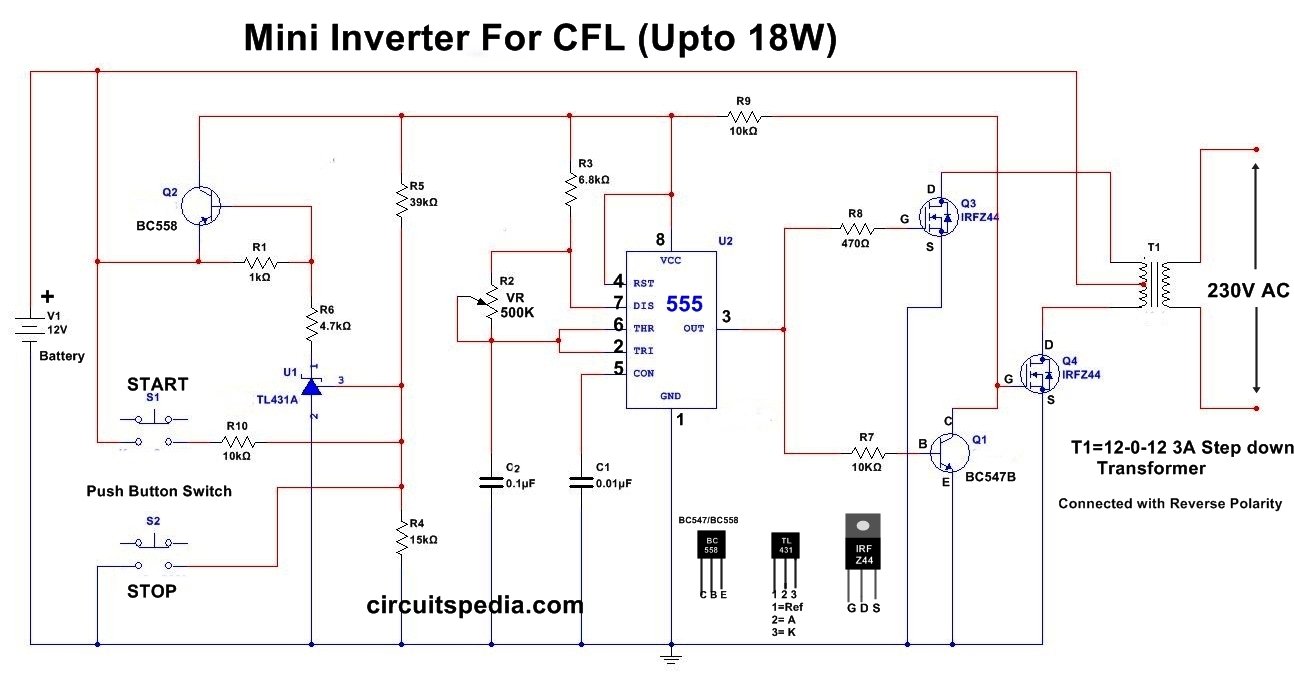
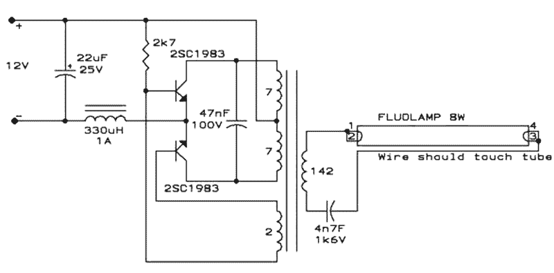
Let s learn about the cfl bulb and ballast circuit diagram with working explanation. This can be used as the emergency cfl lighting cfl needs ac input for operating and this circuit provides the ac to cfl. Circuit explanation of cfl.
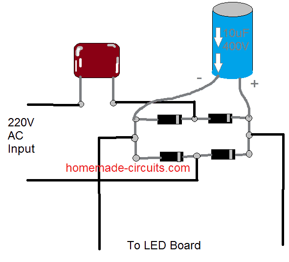
But do you know how does it work construction of cfl bulb ballast circuit diagram. Suppressor for suppressing interference. Bridge rectifier made up of diode 1n 4007.
The pcb of a cfl contains the following key components. The circuit is designed by t kalpana. The complete schematic.
This cfl inverter circuit is operated using the 12v lead acid battery which is mostly used in all homes. Clearly i thank for the help in this question. Key components of pcb of cfl.
The basic construction of a compact fluorescent lamp cfl consists of a fluorescent glass tube that is curved or spiraled and a compact electronic ballast in the base of the lamp. The mains voltage operating range is 200 250 vrms. Completely i share your.


